19XT Transfer Case
I designed, optimized, and manufactured a fully custom transfer case for JHU's Baja SAE team.
Project Overview
In addition to my responsibilities as drivetrain lead, I designed the transfer case of the 2023 Hopkins Baja vehicle, the JH19XT.
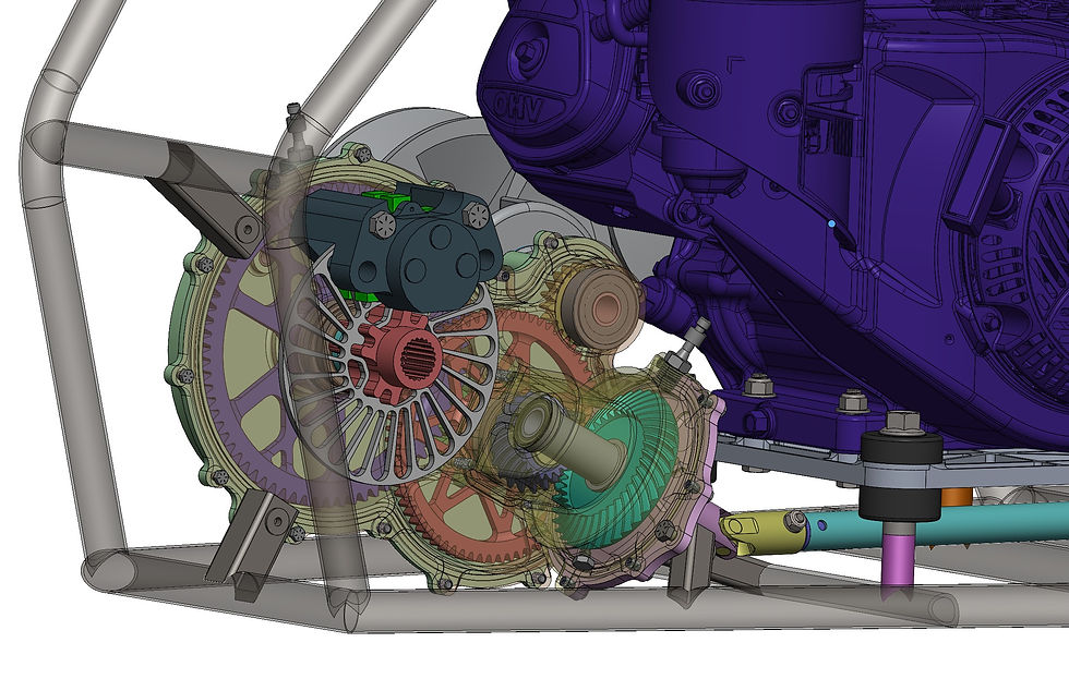
The system architecture consists of a fully custom two-stage spur gear reduction which transfers power from the CVT to the rear axle. Off the middle stage, a pair of custom spiral bevel gears drive the prop shaft to send power to the front differential. On the output shaft, a floating brake rotor and fixed caliper mounted directly to the case provide braking for the two rear wheels.
Once again, my primary design focus was to reduce the number of high risk failure points while also making as many optimizations to reduce weight and rotational inertia as possible. This meant doing thorough analysis on all mission-critical components based on load cases determined through testing and data collection performed on previous vehicles. In addition, I focused heavily on serviceability and minimal dependencies between the 2WD and 4WD components.

Design Highlights
Custom Spur and Bevel Gears
To meet my primary design goals, the transfer case gears were designed to an aggressive 5 hour lifetime, with a brand new set swapped in for each competition. The optimal overall case ratio was selected to best take advantage of the shift range of our CVT while the stage ratios were tuned to reduce mass. The tooth geometry analysis was primarily done in KISSsoft, where load spectra specifically based on our expected drivetrain loading during an endurance race were used to produce gears tuned to suit a Baja vehicle.

Transfer case bevel gear blanks with respective drawings, prior to face milling, case carburizing, and lapping.

Spur gear blanks prior to tooth hobbing and case carburizing.


Gear webbing analysis with fixed center bore and max normal tooth load applied at the pressure angle.
Case Design
Final gear tooth geometry and load spectra were used to derive the loads on each case bearing. These loads, in conjunction with the CVT belt tension load and inboard braking forces, were used to conduct a comprehensive assembly-level study of the case itself as well as all of its frame mounting using ANSYS Mechanical. The main goals of this analysis were to prevent yielding of the case or tabs under normal loading as well as to minimize deflection of the CVT secondary, which would cause efficiency losses and belt wear.
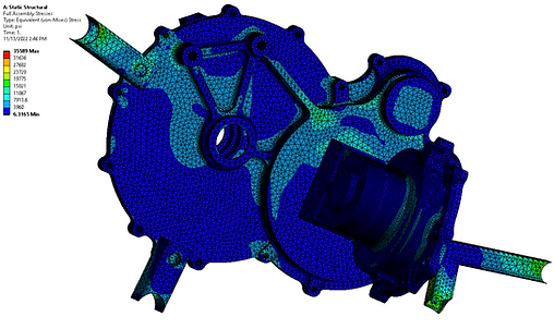
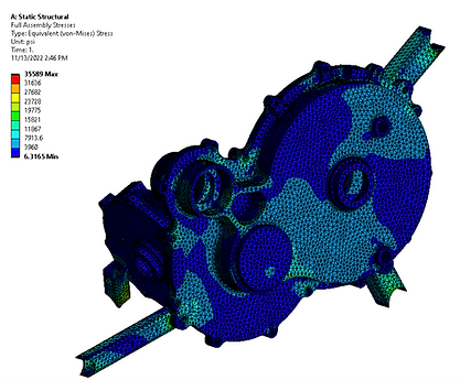
Stress plot of all four case components and rectangular frame mounting tubes. Bearing outer races were included for realistic stiffness and bolted joints were modeled as bonded contact regions in the pressure cone beneath each bolt head. Loads were applied at each bearing contact surface and each frame weld was modeled as a fixed joint.
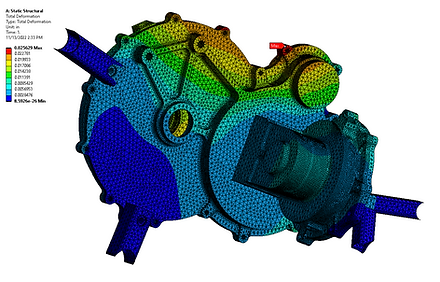
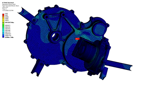
Total deformation and elastic strain plots.